Jay Taylor's notes
back to listing indexeMMC Adventures, Episode 1: Building my own 64GB memory card with a $6 eMMC chip
[web search]Rip It Apart – Jason's electronics blog-thingy
A site dedicated to my hacks, mods, makes and occasional ramblings.
eMMC Adventures, Episode 1: Building my own 64GB memory card with a $6 eMMC chip
There’s always some electronics topic that I end up focusing all my efforts on (at least for a certain time), and that topic is now eMMC NAND Flash memory.
Overview
eMMC (sometimes shown as e.MMC or e-MMC) stands for Embedded MultiMediaCard; some manufacturers create their own name like SanDisk’s iNAND or Hynix’s e-NAND. It’s a very common form of Flash storage in smartphones and tablets, even lower-end laptops. The newer versions of the eMMC standard (4.5, 5.0 and 5.1) have placed greater emphasis on random small-block I/O (IOPS, or Input/Output operations per second; eMMC devices can now provide SSD-like performance (>10 MB/s 4KB read/write) without the higher cost and power consumption of a full SATA- or PCIe-based SSD.
MMC and eMMC storage is closely related to the SD card standard everyone knows today. In fact, SD hosts will often be able to use MMC devices without modification (electrically, they are the same, but software-wise SD has a slightly different feature set; for example SD cards have CPRM copy protection but lack the MMC’s TRIM and Secure Erase commands. The “e” in eMMC refers to the fact that the memory is a BGA chip directly soldered (embedded) to the motherboard (this also prevents it from being easily upgraded without the proper tools and know-how.
When browsing online for some eMMC chips to test out, I found a seller that had was selling 64 GB eMMC modules for $6 Canadian per pop; this comes out to a very nice 9.375 cents per gigabyte (that’s HDD-level pricing right there!). With that in mind, I decided to buy a couple modules and see what I could do with them. A few days later, they arrived in the mail (and the seller was nice enough to send three modules instead of just two; the third module’s solder balls were flattened for some reason).
Toshiba eMMC Module

Calling this board’s operation flaky doesn’t do it justice. It would fail to enumerate 9 out of 10 times, and if I even tried to do anything more than read the device capacity, the reader would hang or the eMMC would drop off the SD/MMC bus and show an empty drive in Windows. It was clear I had to do a full memory card “build” before I could verify the usability of the eMMC Flash memory.
eMMC in an SD Card’s Body: Take 1 (Success… half of the time)
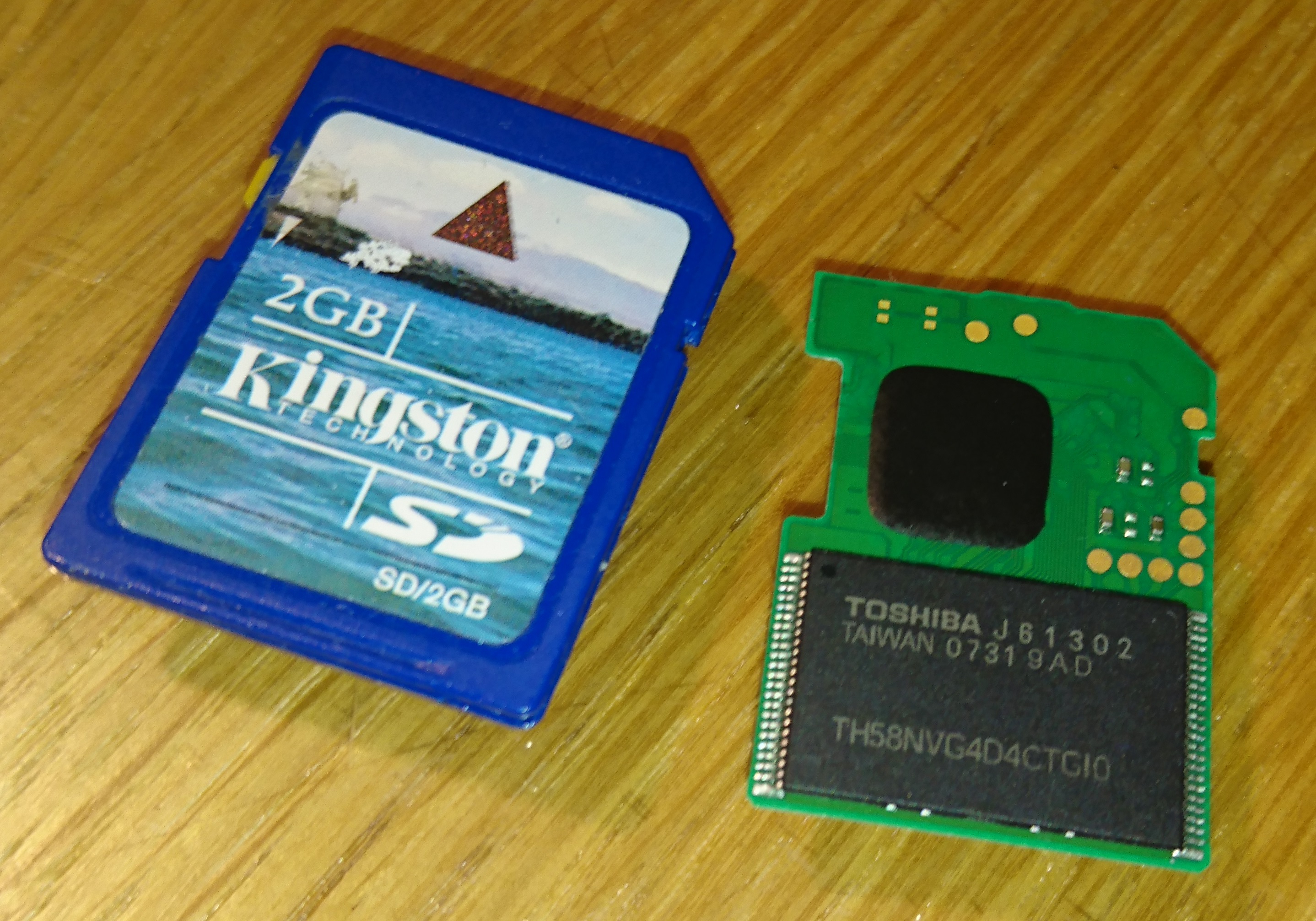
I had a 16 MB (yes, megabyte) SD card lying around somewhere, but as usual, I couldn’t find it among all the clutter around my desk and workspace. Instead, I found an old, slow Kingston 2 GB SD card that I felt would be a worthy “sacrifice” since it was an older type that still had a thin PCB inside (most SD cards nowadays are monolithic, which means it’s one solid chunk with a few pads exposed). After opening up the case carefully with an Exacto knife, I wiggled out the old PCB. I desoldered the orignal 2 GB NAND Flash, and began work on breaking the SD card controller from the PCB as it was a chip-on-board design. It took a while, but I was able to ensure that none of the old SD card hardware would interfere with my rebuild.

I removed the eMMC from the board I made previously, and tested the thickness of it to ensure that it would fit inside the SD card case. It did, although the 0402 surface-mount decoupling capacitors I intended to install would cause a few bumps to be visible through the thin plastic SD card casing.
With my eMMC and SD card pinouts on hand, I used a small bead of epoxy to affix the eMMC to the PCB, balls-side up. I used magnet wire to connect the data lines (4 wires for 4-bit operation which is the maximum that the SD standard supports), and used the unused pads on the eMMC as a kind of prototyping space where I could install ceramic capacitors as close to the module as possible. I used a 0.1 µF 0402 size ceramic capacitor across the VDDi (eMMC internal regulator) and a neighouring GND pad. The rest of the power pads were wired in parallel with a few extra 0.1 µF capacitors added. I made use of the existing three 1 µF capacitors on the PCB as both extra decoupling and connection points for VCC and VCCQ. To prevent shorting of the inner CMD and CLK pins, I only removed the enamel coating from the magnet wire at the very end so I could solder them but avoid the issue of shorting those pins against the other signal and power lines. I then soldered these wires to the terminals on the other side of the PCB.
After spending about ten minutes wriggling the PCB into the SD card casing without damaging the wires, I used a multimeter to ensure all the pins were connected (use a multimeter in diode mode, with the positive lead connected to ground – any valid pins should read ~0.5 volts), and also ensured that there were no polarity reversals or shorts on the power pins.
Now… the moment of truth. At this point my USB 2.0 card reader still wasn’t cooperating with me, so I tried the only other ‘fast’ reader I had at the time – an SD to CompactFlash adapter.

To my relief, I finally got a (mostly) usable card. It appears this particular model has been pre-formatted with FAT32. Viewing the MBR in Hard Disk Sentinel shows nothing notable, apart from the fact that it’s pretty blank and is indicative that it wasn’t formatted for use as a PC boot medium.
Things began to fall apart after I tried running speed tests, as the card would hang if it experienced a lot of write activity at once. I suspected this was a power supply-related issue, so I modified my layout to add more capacitance. For good measure, I added 56 ohm termination resistance for the DAT0-4 data lines, using a small resistor network harvested from an old dead MacBook motherboard.
After these modifications, performance was much, much better. Now that the card was usable, I could finally run some speed tests.
eMMC in an SD Card’s Body – This time, with more feeling decoupling!
After adding several 100 nF and 1uF 0402-size ceramic capacitors on the eMMC package, I was able to get a stable card that could be read by (most) SD card readers. As I was rather anxious to get a decent benchmark from the eMMC, I decided to forego the cheaper Amazon Prime route, and go to my local PC parts store to buy a USB 3.0 card reader – the Kingston FCR-HS4.
After placing the eMMC and SD card PCB back into its plastic casing, I was relieved to see that Windows immediately recognized its presence. All I had to do then was open CrystalDiskMark and run the benchmark. Drum roll please…

Out of the Reader and Back Into the (CF) Adapter
Now that I know what the eMMC is capable of, I decided to try putting it back into my SD-to-CF adapter and doing another benchmark.

 Jason
Jason
-

 very nice article and good job on the project. I am trying to find pin out on the Toshiba nand and I was wondering if you came across or know how to find because I have searching and searching and I cant find out data-set or pin out on this nand its a emmc TOshiba TH58NVG7D7FBASB. If you come across or can find one please let me know. Thanks again and keep up the good work
-
 Thanks for your reply. I have question and was wondering have you ever tried to used NAND from cellphone as USB drive. Like taking off NAND flash memory of old phone and install it on USB drive board and use it as flash drive? I bought some blank flash drive board from web which have ISO902 controller and I tried to solder on NAND memory from dead iPhone but when I plug it in to pic or Mac it does not recognize the flash drive and if I insert flash drive without NAND chip soldered it recognizes the flash drive but since no nand chip soldered on board it does not show on computer. I think it’s controller related issue like controller does not support that lga52/60 NAND if I am right do they have some cross referencing chart like which controller support tjoshiba ,hyxi, or scan disk memory. Like the refrence sheet you have for toshiba memory ??
Another question have you tried the wafer that has one side like as card contacts and other side which has NAND memory pads on which you can mount lga52/60 or other kind of memory? Do you know like cross over connection for SD card contacts to NAND I was thinking of making a homemade board
Thanks again for your reply for last post

 do you know any manual way of identifying pin on a NAND memory chip?
-

 I’ll continue to wire the socket, but not use it until either I hear back or I chance it.
Thanks,
Unferium-
Jason
-
 Jason
Jason

 Joao
Joao
-
 Jason
Jason
 Hard coded chip requirement in ROM/UEFI*,
Requirement for boot partitions by the UEFI/”BIOS”,
bad wiring (Checked many times throughout so unlikely),
an internal eMMC pullup on a higher up DAT# being required by the UEFI^,
a detect pad (checked that first of all things, so nope)^Problem is I’ve already layered over the eMMC footprint for the SD card holder to seat making modifying >DAT4 harder.
*note on first suspicion… Linux 4.10 reports, “new high speed SDIO card at address 0001”. I insert a 128GB SD card in the unbootable main (end user, stock) SD card slot and it says the same thing along side allocating “mmcblk2” thus proving at least the internal non-existing eMMC slot has been reserved.
Don’t know what to do with the tablet as linux doesn’t support the bespoke sound IC or the WiFi and I can’t restore windows on it without the eMMC chip.
-
 Try visiting turn Monday if you wish.
USB:
This tablet has 2x end-user physical USB ports, OTG mini-USB and the docking keyboard. The docking connection is actually 2x USB ports 1x full size USB and 1x USB data for the keyboard.
I’m booting a live 32bit-EFI compatible 32/64Bit hybrid Linux/GNU distro via the docking USB for testing.Card tests:
Tried both with the card in and out of the modded slot, Linux reports a card exists but not initialized on the first MMC controller.Windows installer:
Tried diskpart, no-go, tried the load drivers… loads drivers and won’t show the SD card.Hopefully that answers most questions,
P.S.
I have a 64GB eMMC kicking around that I’ve started to convert to an SD card…
I might restore windows to that and jump-lead it on deadbug style as I’m useless at BGA for now, however It’ll likely take damage in use as there isn’t much room in the tablet PC. It however, will determine if the UEFI has been hard-coded for the stock chip or not. http://sites.google.com/site/unferium/w10x86alcatel
Still under construction, so it is a very rough cut

 https://ibb.co/jq4G2v
https://ibb.co/dpyb2vAlso can I replace the chip with a 128G chip (as can be seen having the same BGA pinout as 64GB) , and is it necessary to have the same FORSEE EMMC or we can choose another much reliable EMMC brand with the same specs (and possibly greater size).
Lastly if it is possible, since I am not an expert in it neither do I have the tools for the same. Is there a professional service online to whom I can send the motherboard (or the whole tablet in case needed) for repair. Hopefully the bootloader code shouldnt be hampered by the EMMC replacement.
I recently bought this tablet and although it seems like a wasted cost, am still willing to do this experiment to revive and reuse the tablet instead of buying a new one.
Would really appreciate all the guidance and help.
-
-
-


